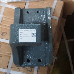
rear spring block
| Products | description | role |
| V V Base | Middle position of axle housing | Fixed mounting thrust rod |
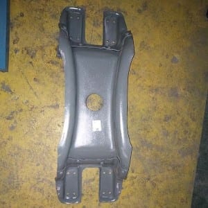
| V Rod assembly | ,One side mounted on the axle housing, the other side mounted on the frame | Drive axle front and rear fixed |
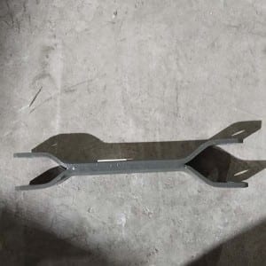
| Cross member | Below the gearbox | Support the transmission |
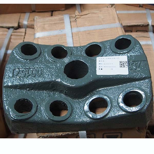
| rear spring block | Above the leaf spring | Tighten and press the leaf spring through the riding bolt |
| brake liner | Upper brake shoe | Friction with the brake hub produces braking resistance |
| Transmission shaft | Between the transmission and the rear axle | power transfer between rear axle and transmission |
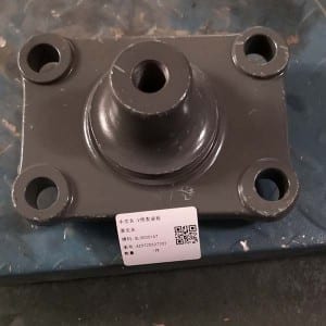
| Strut block | Central frame | Stationary engine |
| spring | above the Balance shaft shell | Plate spring shock absorption of the vehicle |
| spring | above the Balance shaft shell | Plate spring shock absorption of the vehicle |
| rear spring Bracket | Frame the back-end | lift the steel plate assembly |
| U rear spring U-bolt | Steel plate center | Fixed leaf spring |
| Plate assembly | the back-end of the Frame | lift the stabilizer |
| Rotating shaft | cab component | as a fulcrum for the cab |
| Flange nut | ||
| Housing | The outer side of the equilibrium shaft shell | Sealed and dust proof |
| Balance shaft assembly | Between the steel plate and the frame | The support of the frame |
| Draught base | the back-end of the Frame | Occupy the trailer |
| U front spring U-bolt | Steel plate center | Fix leaf spring |
| front spring rear Bracket | both ends of Steel plate | Support, connect and fix steel plate |
| Hanger assembly | Frame front left and right sides | Steel plate assembly before lifting |
| Plate | Above the leaf spring | Tighten and press the leaf spring through the riding bolt |
| front oil seal | The crankshaft front terminal | Sealing |
| Flange plate | The shaft | Connect the drive shaft |
| V push rod ball joint bearing | Thrust bar ends | Fixed and damped |
| push rod repair kit | Thrust pole | repair thrust bar |
| Rod assembly | ,One side mounted on the axle housing, the other side mounted on the frame | Drive axle front and rear fixed |
| Universal Joint Bearing | The flange of the drive shaft is inside the fork | Direction change of drive shaft |
| Stabilizer bar assembly | Front axle ahead | Stable and balanced vehicle |
| Brake shoe spring | Between the brake shoes | Brake shoes return to position |
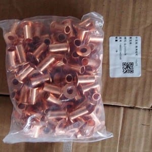
| Rivet | ||
| Brake camshaft Bracket | Rear axle left and right ends with rear brake baseplate | Install rear brake camshaft |
| middle axle bearing Plate | ||
| steering pump | Camshaft timing gear cover | Add power to the steering system |
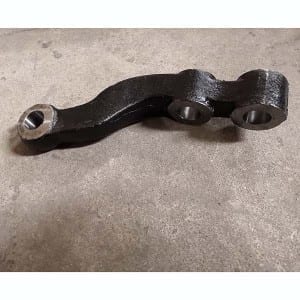
| Tie rod arm | Steering knuckle | ,Connect the knuckle and the steering link ,to change the direction of force transfer |
| Steering knuckle arm | Steering knuckle | Connect the steering straight tie rod |
| Bracket assembly | ||
| Tie rod assembly | Front wheel knuckle | control Steering wheel left and right rotation |
| Ball joint | Steering wheel left and right rotation control | Transfer power |
| Steering shaft with column assembly | Under the wheel | The output force and motion of the steering gear are transferred to the steering wheel ,to deflect the two steering wheels so as to realize automobile steering |
Write your message here and send it to us